I’ve just uploaded a new video showing two Libre Tag guns, one shooting the other.
I’ve just uploaded a new video showing two Libre Tag guns, one shooting the other.
I have posted the circuit diagram for the current version of the Libre Tag system:-
Since I first built a working circuit for the LibreTag project, I always found that testing indoors proved to be without any need of aiming. My walls are white and so much IR is generated by the IR LED,that you can almost point the gun in any direction and score a hit.
I have been thinking of ways to be able to scale the power output of the guns down depending on where you intend to use them. My best idea so far was to use another FET to switch the IR LED either through a ~100 ohm resistor or straight to ground, to give a x1 or x1/10th power selection. However the problem with this is that it would never give you a chance to say scale from a large room to a small room.
Tonight I had a brain wave. After glancing over the data sheet for the 38khz IR receivers I noticed that they have a fairly high drop off as the frequency diverges from 38khz. I wondered if I could use this to my advantage by changing the PWM frequency of the transmitting IR LED.

I am happy to report it works wonders. I still need to implement a menu option to make the “strength” selectable, but with the freqency set to 50khz the sensitivity of the receiver, as per the graph, drops down to about 20%. It makes the gun usable indoors, with no sign of any reflections. It is maybe a little too under powered at 50khz, but this can be tweaked.
Work has been progressing rather slow recently. I’ve been very busy and just haven’t had the time to do some serious work on the guns. Coupled with the shorter days and awful weather we have been having in the UK the last few weeks, means I havn’t had a chance to go outside to do wood work / painting.
However I have more or less finished one gun now, with another 2 not far behind.
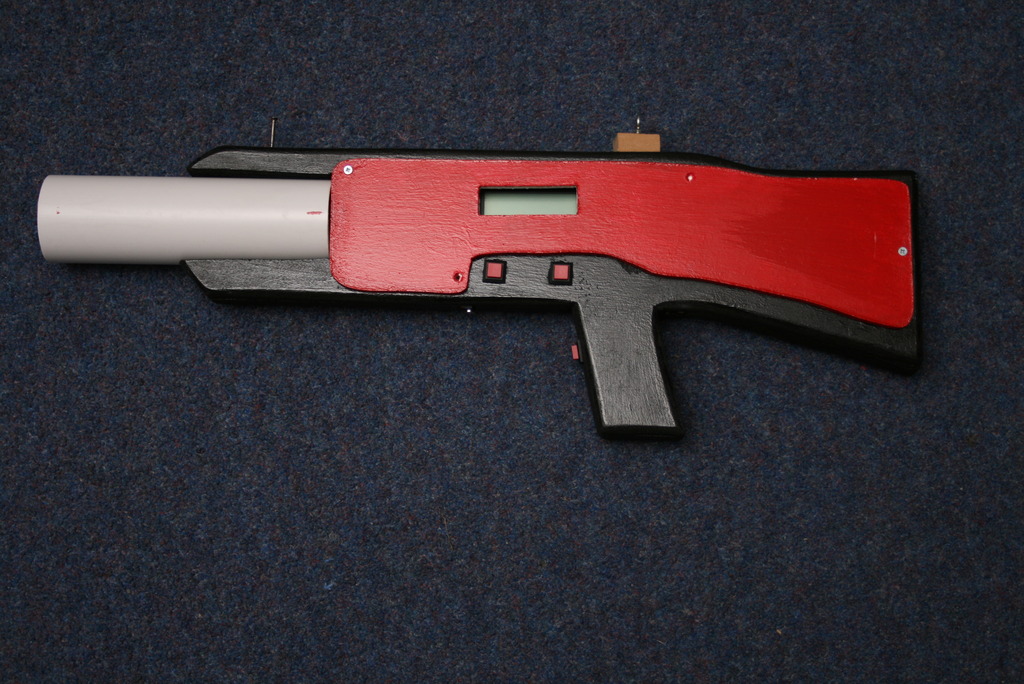
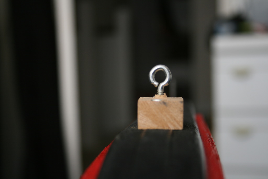
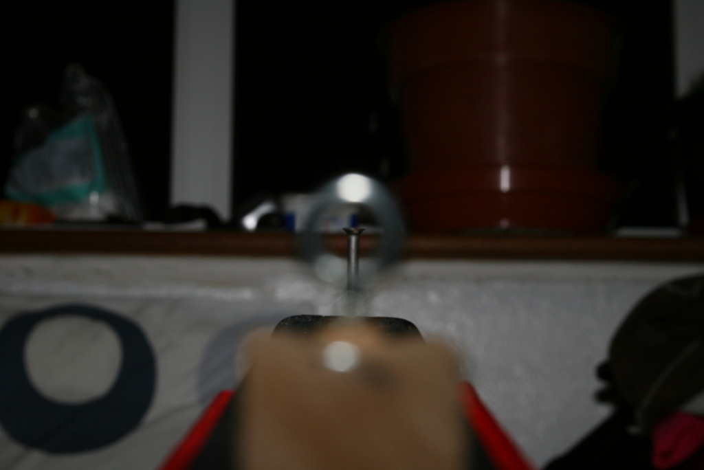
As you can see I’ve painted them with a large red side, this is so they comply to the VCRA (Violent Crime Reduction Act). It sad that we have to do such things, but better safe than sorry. I have also been experimenting with different types of sights and have attached a prototype one to the gun. It seems fairly accurate, I was easily able to aim perfectly from over 100ft. I will be testing some other types of sights in the coming weeks and hope to post a article comparing them.
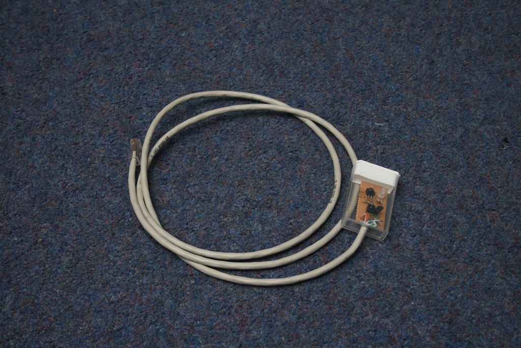
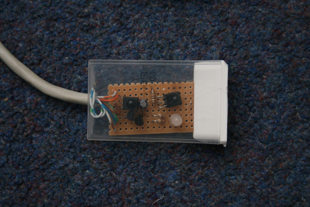
The last two pictures are of the sensor. It is mounted in a Tic Tac box, which seems to be a pretty good fit. There will eventually be 3 sensors per gun, but I need some more people to eat Tic Tacs first.
Code wise, not much has changed. I have tidied up some of the code and made a few corrections to the parity encoding/decoding which has reduced the number of corrupt virtual bullets. It seems good enough now, with only one being received every 30-60 shots.
I have posted some pictures I took during the construction of the prototype gun here:-
http://www.fisk.me.uk/blog/laser-tag-libre-tag/guns/prototype-gun/
I will update the page in the near future with some more information regarding the gun.
I have uploaded two more videos to youtube showing some features I have just added
Reloading and showing burst and single shot modes
Showing the menu system
After what seems like too many hours, I have finally assembled the first Libre tag gun.

The exposed circuit at the top of the gun is a sensor, I need to put a RJ45 socket on the gun so that the sensor can be attached properly, but that is a minor task. The only other task is to mount a IR LED and lens into the lens assembly and mount it on the gun.
Below is a short video of it in action:-
I’ve have been busy assembling the components the scouts made at our last rocket construction evening. I have now coupled everything together to effectivly leave us with the compelted structure of the rocket.

A 15mm plastic tube is used as a skeleton onto which the boosters are duct taped onto. I decided to use duct tape in the end as it seems to have massive sticking power. It is stuck down the whole length of the plastic tube and provides a very stiff booster segment. The multi-stage part of the rocket then slides down on to an exposed part of the tube sticking out the stop of the booster.
I weighed the whole rocket as pictured above and it came to just slightly over 800g.
More updates with finer details of its construction to come over the next week.
Now that I have finally come up with a relativly easy method of butt joing bottles, I sat down this weekend and made another two butt to butt joined sections. I have that it is extremely important to make sure that the holes in the bottom of the bottles are perfectly central, otherwsie the ridges on either bottle will not sit together properly. This will in turn mean that the actual centre of the bottles are not touching and thus your little piece of threaded rod, will not be long enough.
Now that I have 3 completed sections, I can start to construct the bottom half of our new rocket, which will be a booster cluster comprised of 3xrockets. For demonstration purposes I have held the 3 sections together with elastic bands.

You can see I have placed the staging mechanism on top of the boosters. There will probably be another section inetween them, which contains the electronics and parachutes for the booster section.
After trying many times to get a working air tight pressure switch using the brass components in the previous post, I decided that it wasn’t going to happen. So I set about trying something new.
I stumbled across this on the Yahoo water rocket forums:-
http://groups.yahoo.com/group/water-rockets/photos/album/930791471/pic/list
I decided that this looked like a very reliable method of making a pressure switch. The only down side is that it needs to screw onto the top of the bottle, this means that you need to join the bottles together by bottoms, instead of the normal top to bottom arrangement.
I am glad to see, as you can see below that the new switch works really well and there is no sign or any leaks. The switch operates at about 20psi, slightly higher than the previous design, but probably due to the slightly thicker rubber.